AMAZON multi-meters discounts AMAZON oscilloscope discounts
The pneumatic-assisted valve operates on a simple principal of counterbalance. Ill. 1 shows a diagram of the basic parts of this type of valve actuator and electrical-to-pressure converter that's called an I/P transmitter because it converts a milliamp signal to variable pressure. The top part of the diagram shows the converter, and the bottom left part of the diagram shows the pneumatic-operated valve.
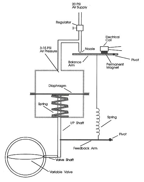
Above: Ill. 1: Simplified diagram of a pneumatic-assisted valve with
an electric-to-pneumatic signal converter.
The main part of the converter is a balance beam. The balance beam is balanced on the beam pivot. Air from a nozzle is directed on the left end of the beam, which tends to push this end of the beam down. A coil that produces an electromagnetic field and a permanent magnet are connected near the middle of the beam. When the coil is energized and it produces a strong magnetic field, it will tend to pull the beam up. This will cause a force that opposes the air flow directly on the end of the beam. The stronger the current in the coil is, the stronger the magnetic field becomes and the more the beam is pulled tighter against the air nozzle. This will cause the beam to restrict the flow of air coming from the nozzle.
A tube is connected at a T connection near the tip of the air nozzle. This tube provides air to the diaphragm of the pneumatic-actuated valve. The amount of air pressure on the diaphragm of the valve will counter the spring pressure inside the valve that pushes the diaphragm up. The difference of the air pressure and spring pressure inside the valve will determine the position of the diaphragm, which will in turn determine the position of the valve stem somewhere between full open and full closed.
The valve mechanism for this valve is not shown. It would be connected to the end of the valve stem at the bottom of this diagram, and it would move up and down into a valve seat. The position of the valve mechanism can be anywhere between completely in the seat, which would shut off all flow through the valve, to completely up out of the seat, which would allow complete flow. A rod is connected to the valve stem that provides a feedback signal. This rod is normally connected to some type of positional sensor like a linear potentiometer or LVDT to convert the positional data to an electrical signal.